Relays
Properly known as an electromagnetic armature relay to distinguish it from a solid-state relay. However, the full term is very rarely used. It may also be described as an electromechanical relay, but the term relay is normally understood to mean a device that is no solid state.
A relay enables a signal or pulse of electricity to switch on (or switch off ) a separate flow of electricity. A relay contains a coil, an armature, and at least one pair of contacts. Current flows through the coil, which functions as an electromagnet and generates a magnetic field. This pulls the armature, which is often shaped as a pivoting bracket that closes (or opens) the contacts.
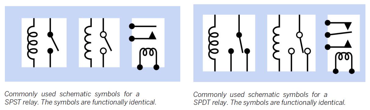
Figure 1: SPST (single-pole, single-throw) relay symbols vs. SPDT (single-pole, double-throw) relay symbols.
Latching
There are two basic types of relay: latching and nonlatching. A nonlatching relay, also known as a single side stable type, is the most common, and resembles a momentary switch or pushbutton in that its contacts spring back to their default state when power to the relay is interrupted.
By contrast, a latching relay has no default state. Latching relays almost always have doublethrow contacts, which remain in either position without drawing power. The relay only requires a short pulse to change its status. In semiconductor terms, its behavior is similar to that of a flip-flop.
Pinout
The layout and function of relay pins or quick connects is not standardized among manufacturers.
Values
Datasheets usually specify maximum voltage and current for the contacts, and nominal voltage and current for the coil, although in some cases the coil resistance is stated instead of nominal coil current.
The minimum voltage that the relay needs for activation is sometimes described as the Must Operate By voltage, while the Must Release By voltage is the maximum coil voltage that the relay will ignore. Relays are rated on the assumption that the coil may remain energized for long periods, unless otherwise stated. While the contact rating may suggest that a relay can switch a large load, this is not necessarily true if the load has significant inductance.
Schematics
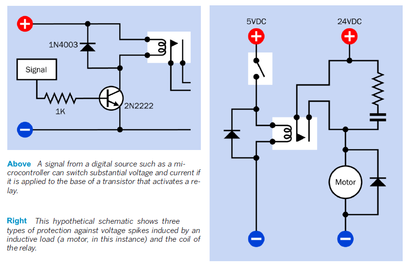
Figure 2: A common small-scale application (above) in which a signal from a microcontroller (a few mA at 5VDC) is applied to the base of a transistor, which controls the relay. In this way, a logic output can switch 10A at 125VAC. Note the rectifier diode wired in parallel with the relay coil.
Right, a circuit including every possible protection against voltage spikes, including a snubber to protect the relay contacts, a rectifier diode to suppress back-EMF generated by the relay coil, and another rectifier diode to protect the relay from EMF generated by a motor when the relay switches it on and off.